Configure Source Collections from DI Perspective
Data Fusion is in Beta. Please contact your C3 AI representative to enable this feature.
In earlier versions of C3 AI Studio, you configured the entire data ingestion pipeline manually, from the source system all the way to the target entity.
This involved defining multiple layers in sequence:
SourceSystem → SourceCollection → Source → Canonical → Entity
With the latest enhancement, you can now configure data sources directly from the Data Integration (DI) perspective, in the Data Fusion tab of C3 AI Studio, eliminating the need to switch to the Data Sources perspective.
This feature streamlines the workflow by stitching together existing data pipelines.
If an application already includes a partially built pipeline (for example, Canonical → Entity), you only need to configure the missing upstream components:
SourceSystem → SourceCollection → Source
Benefits
- Simplifies configuration by leveraging existing canonical-to-entity mappings.
- Provides a unified, visual configuration experience within the graph view.
- Reduces manual setup time by allowing users to define only the necessary upstream connections.
When to Use This
Use this method when your Canonical and Entity types already exist, either in your application package or in a dependency package, and you only need to define the upstream data flow (for example, Source System and Source Collection).
This approach is ideal for extending partially built pipelines or onboarding new data sources into an existing data model without redefining canonical or entity types.
Prerequisites for Configuring a Source Collection from the Data Integration Canvas
Before you configure a Source Collection directly from the Data Integration (DI) canvas, ensure the following prerequisites are met:
A valid mapping path from Source → Target must exist.
The DI canvas connects nodes based on available type mappings defined in your application or its dependency packages.
This mapping can take various forms, for example:
SourceCollection → Canonical Canonical → Entity
Without a valid mapping, the system cannot determine how data should flow, and the Unconfigured node will not appear.
A Target Type (Canonical or Entity) must exist and be deployed.
- The DI canvas builds upon existing target types to help you configure the upstream data flow.
- The Source node and mapping logic are created during configuration.
- Although the DI canvas can render without the entity and transform, the pipeline will fail during execution if they are missing.
A Source System must already exist in your environment.
- You must define and configure a Source System (for example, an S3 bucket, database, or API connection) under the Data Sources tab before it can be referenced in the DI canvas.
- The DI configuration process reads from these defined Source Systems when adding a new Source Collection.
Add a Data Source
Navigate to Data Fusion → Data Integration.
In the graph view, select an Unconfigured node.
From the Data Sources panel on the left, choose an available data source.
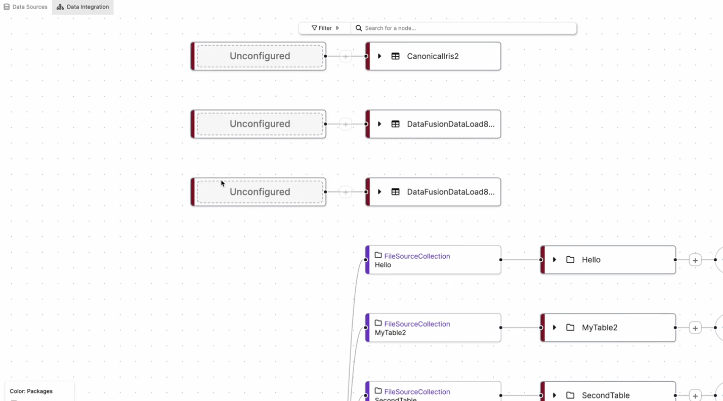
In the example above, the Unconfigured nodes represent new data sources that must be defined. Once the user links a data source, C3 AI Studio automatically integrates it into the pipeline, connecting it to the pre-existing canonical or entity objects.
Open and Configure the Source Collection
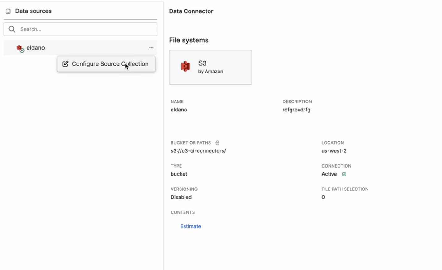
In the Data Integration perspective, expand the Data Sources panel on the left.
The Data Connector details appear, displaying:
- Connector Type (for example, S3 by Amazon)
- Bucket or Path (for example,
s3://c3-ci-connectors/) - Location, Connection Status, and Versioning information
Hover over the desired data connector and select the ⋯ (More options) icon.
Select Configure Source Collection.
This option allows you to create or edit a Source Collection directly within the DI graph view.
Begin configuration as prompted in the canvas.
Select the Data Path
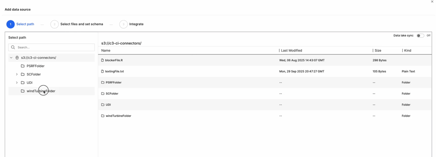
In the Add Data Source dialog, browse through your connector’s directory structure.
Choose the appropriate path or folder (for example,
windTurbineFolder/).Confirm your selection and click Next.
This step defines the location from which data will be ingested into the platform.
Define the Schema
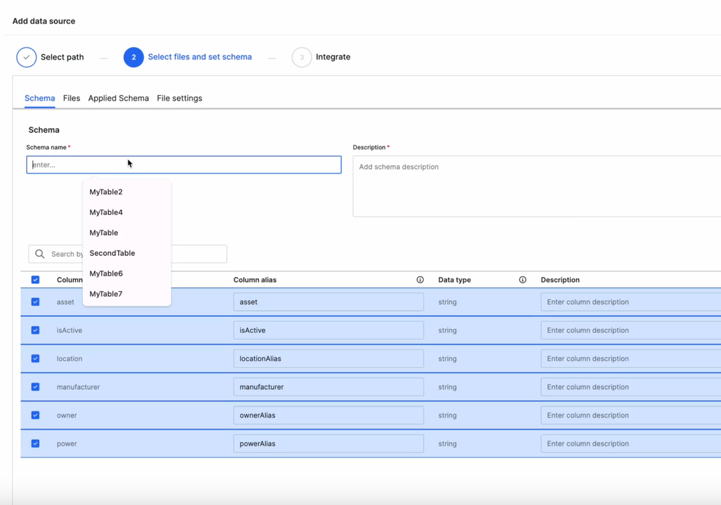
In the Select Files and Set Schema step:
- Enter a Schema Name and a short Description.
- Review the detected columns and modify as needed.
- Update Column Alias, Data Type, and Description fields.
You can reuse an existing schema (for example,
MyTable,SecondTable) or define a new one.Select the required columns for ingestion and select Next.
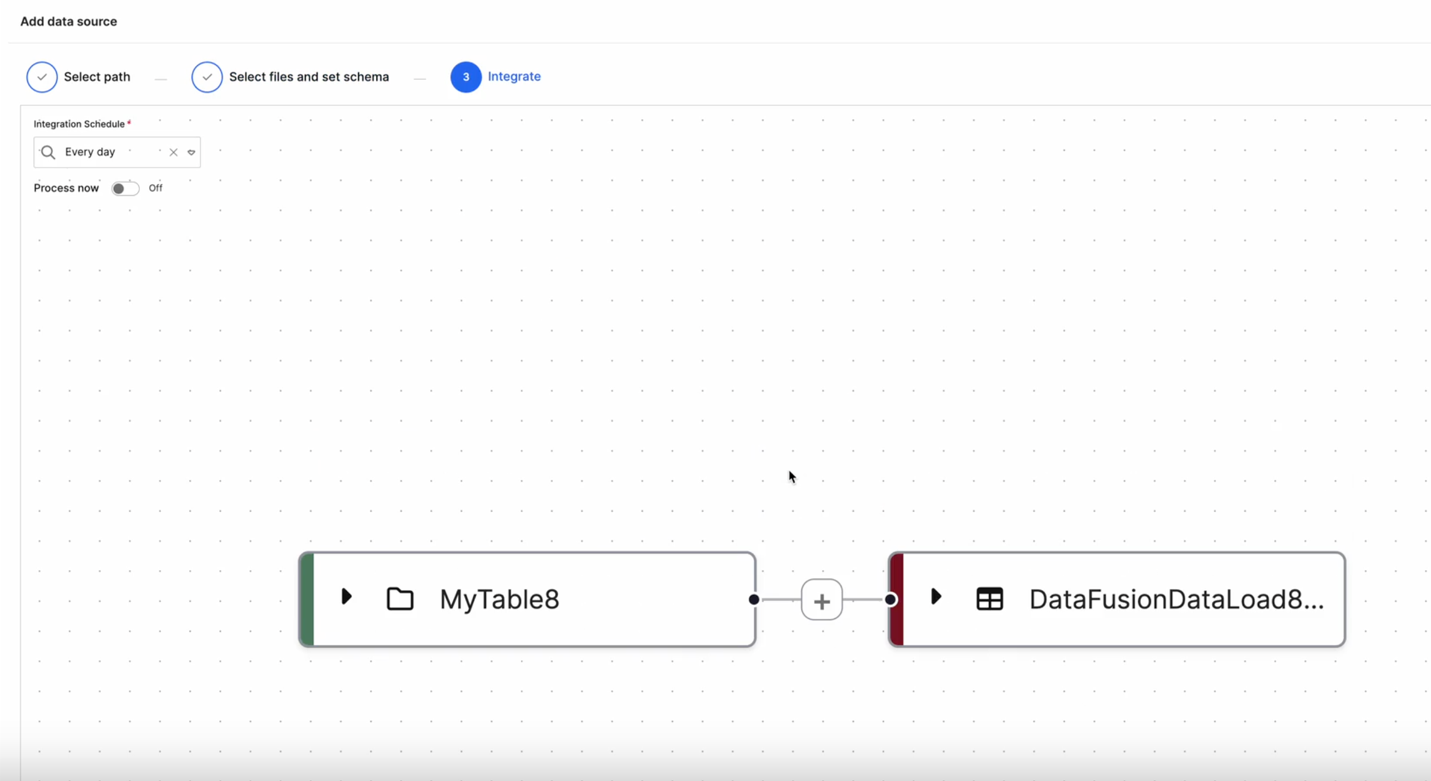
Integrate and Schedule
In the Integrate step:
Define an Integration Schedule (for example,
Every day) to control ingestion frequency.(Optional) Toggle Process now to trigger immediate ingestion.
Review the connection on the graph view — the new source node (for example,
MyTable8) appears automatically connected to its corresponding Data Load node (for example,DataFusionDataLoad8).
Apply Transformations
To further refine your data before loading, select the (+) icon between the Source and Target nodes.
Choose a Transformation Type:
- Projection – Select and reorder columns.
- Transformer – Apply formulas or transformation logic.
- Filter – Define record inclusion or exclusion rules.
Save the configuration.
The new Transformation node appears in the pipeline.
Map Source Fields to Canonical Fields
After defining your schema and integration schedule, select the Transformer option to map your source data fields to the target canonical or entity fields using the Transform Code Editor.
This step ensures that data ingested from your source follows the structure and requirements of the target model in C3 AI Studio.
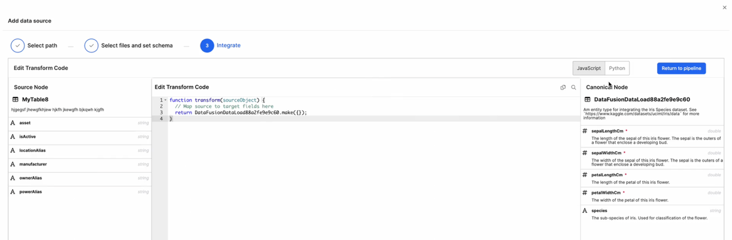
Source Node Panel (Left) - Displays the list of fields available from your source schema (for example, MyTable8). Each field includes its Name, Alias, and Data Type.
Code Editor (Center) - Lets you define transformation logic in JavaScript or Python. The transform() function maps each field in the source object to the corresponding target field. By default, a simple template is provided:
function transform(sourceObject) {
    // Map source to target fields here
    return DataFusionDataLoad88a2fe9e9c60.make({});
}
Canonical Node Panel (Right) - Displays the structure of the target canonical entity (for example, DataFusionDataLoad88a2fe9e9c60). Each field lists its Name, Data Type, and Description. The required fields are marked with a red asterisk (*).
Map Fields
- In the Code Editor, update the mapping logic to align source fields with target canonical fields.
function transform(sourceObject) {
    return DataFusionDataLoad88a2fe9e9c60.make({
        sepalLengthCm: sourceObject.asset,
        sepalWidthCm: sourceObject.locationAlias,
        petalLengthCm: sourceObject.manufacturer,
        petalWidthCm: sourceObject.powerAlias,
        species: sourceObject.ownerAlias
    });
}
Choose your preferred language (JavaScript or Python) using the toggle at the top.
Select Return to Pipeline to go back to the graph view once your mappings are complete.
After saving, the Transformer node appears between your Source Collection and Canonical nodes in the pipeline.
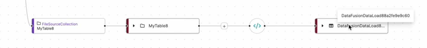
This visual link confirms that the data transformation logic has been successfully defined and the mapping between source and target entities is established.
Once configuration is complete:
The graph view visually updates to show your connected data flow.
The previously Unconfigured node now displays the configured Source Collection.
Data flows seamlessly from the defined source to its Data Load, Canonical, and Entity targets.
This integrated workflow allows users to define, transform, and schedule data ingestion directly from the Data Integration perspective, providing a unified and intuitive experience.