Connect with SQL Source System
Your Snowflake database holds tables that your C3 AI application needs. Data Fusion connects to Snowflake and loads those rows into an entity Type in your application. You build the pipeline on the Data Fusion canvas, where each stage of the pipeline appears as a node that you select to configure.
Snowflake is the worked example on this page. Other SQL database connectors, such as Postgres and SQL Server, follow the same steps with their own connection fields. Some SQL connectors add an Advanced step for optional settings.
The screenshots on this page use a sample Snowflake table, read by a source collection named demoTableColl. Use your own table, collection, and Type names.
To build the pipeline, you configure these canvas nodes in order:
- SQL Source System: the connection to your Snowflake account (SqlSourceSystem).
- SQL Source Collection: one Snowflake table that the pipeline reads (SqlSourceCollection).
- External Entity Type: the columns and data types of that table. The node holds an entity Type that mixes External, so the Type describes rows that stay stored in Snowflake.
- Transform: the field mapping from that Type to the target entity Type (Transform).
- Entity Type: the target entity Type, where the pipeline stores the loaded records in your application.
You then choose how the source collection loads data, run the pipeline, and check the loaded records. If the connection test fails, Troubleshoot a failed connection test lists the errors the wizard reports and how to fix each one.
Prerequisites
Before you start, make sure you have:
- A C3 AI application where you can open Data > Data Fusion in C3 AI Studio.
- Network access from your C3 AI environment to your Snowflake account.
- A Snowflake user that can use the warehouse and read the database you plan to connect.
Collect these values from your Snowflake administrator:
- Account URL: your Snowflake account address, for example
your-account.snowflakecomputing.com. - Database and Warehouse: the database that holds your table and the warehouse that runs the queries.
- Schema (optional): the default schema to use.
- Username: the Snowflake user that the connector signs in as.
- The credential for one authentication method:
- Key Pair: the user's private key in PEM format, and its passphrase if the key is encrypted. The matching public key must be registered for the Snowflake user.
- Programmatic Access Token: a programmatic access token issued for the Snowflake user.
The connector signs in without user interaction, so it offers these two methods and no password sign-in. For how to generate either credential, see the Snowflake documentation: Key-pair authentication and key-pair rotation and Using programmatic access tokens for authentication.
Add the Snowflake source system
The connector wizard creates the SQL Source System node. The wizard has four steps: Connector, Destination, Authentication, and Review.
Open the connector wizard
Start from the Data Fusion canvas in your application:
- In C3 AI Studio, open your application and select Data > Data Fusion.
- On the Data Integration tab, select Add Data Source. The Configure Connector sheet opens.
- Under Database & data warehouse, select Snowflake, or search for it. The wizard opens on the Destination step.
Enter the connection details
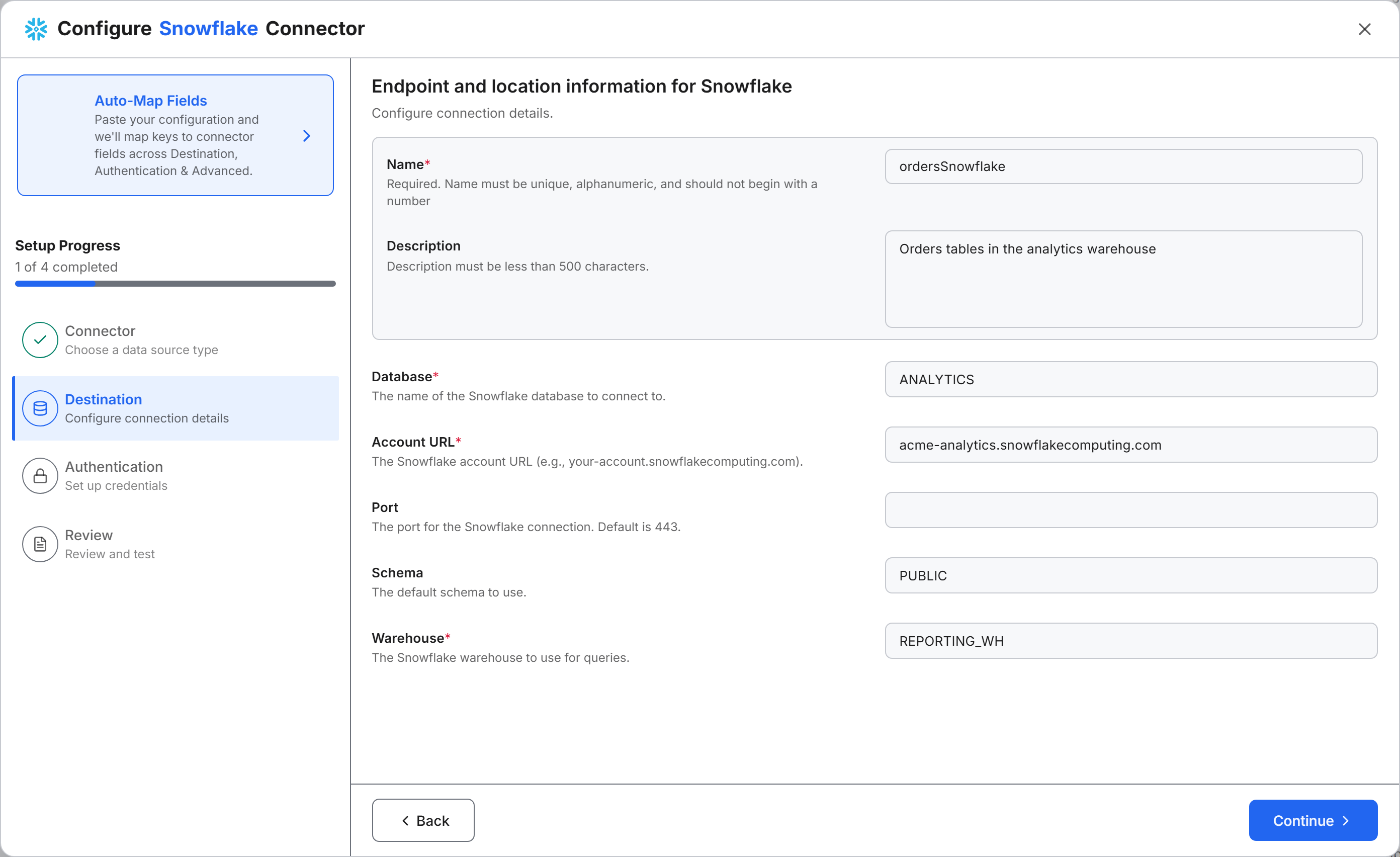
On the Destination step, enter the connection details:
- Name: a unique name for the connector. Use letters, numbers, and underscores, and do not start with a number.
- Description (optional): fewer than 500 characters.
- Database: the Snowflake database to connect to.
- Account URL: your account address, for example
your-account.snowflakecomputing.com. - Port (optional): leave it blank to use the default, 443.
- Schema (optional): the default schema to use.
- Warehouse: the Snowflake warehouse that runs the queries.
Select Continue.
Enter the credentials
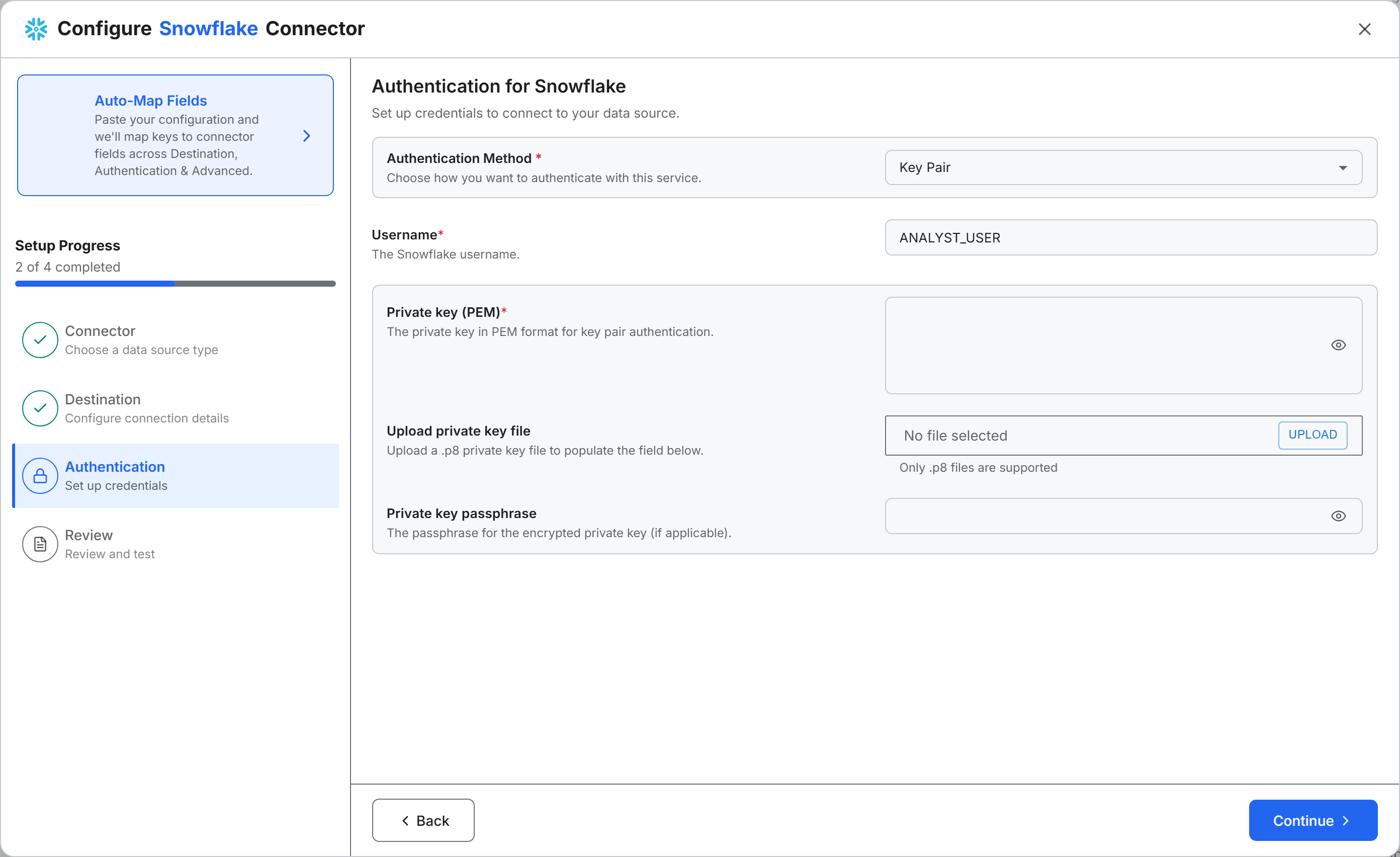
On the Authentication step, choose an Authentication Method and enter its credentials:
- In Authentication Method, select Key Pair or Programmatic Access Token.
- In Username, enter the Snowflake user name.
- Enter the credential for the method you selected:
- For Key Pair, paste the full PEM text into Private key (PEM), including the
BEGINandENDlines. To load the key from a.p8file instead, select UPLOAD next to Upload private key file. If the key is encrypted, its first line is-----BEGIN ENCRYPTED PRIVATE KEY-----; enter its passphrase in Private key passphrase. Leave the passphrase blank for an unencrypted key. - For Programmatic Access Token, paste the token into Programmatic access token.
- For Key Pair, paste the full PEM text into Private key (PEM), including the
- Select Continue.
Test and save the connector
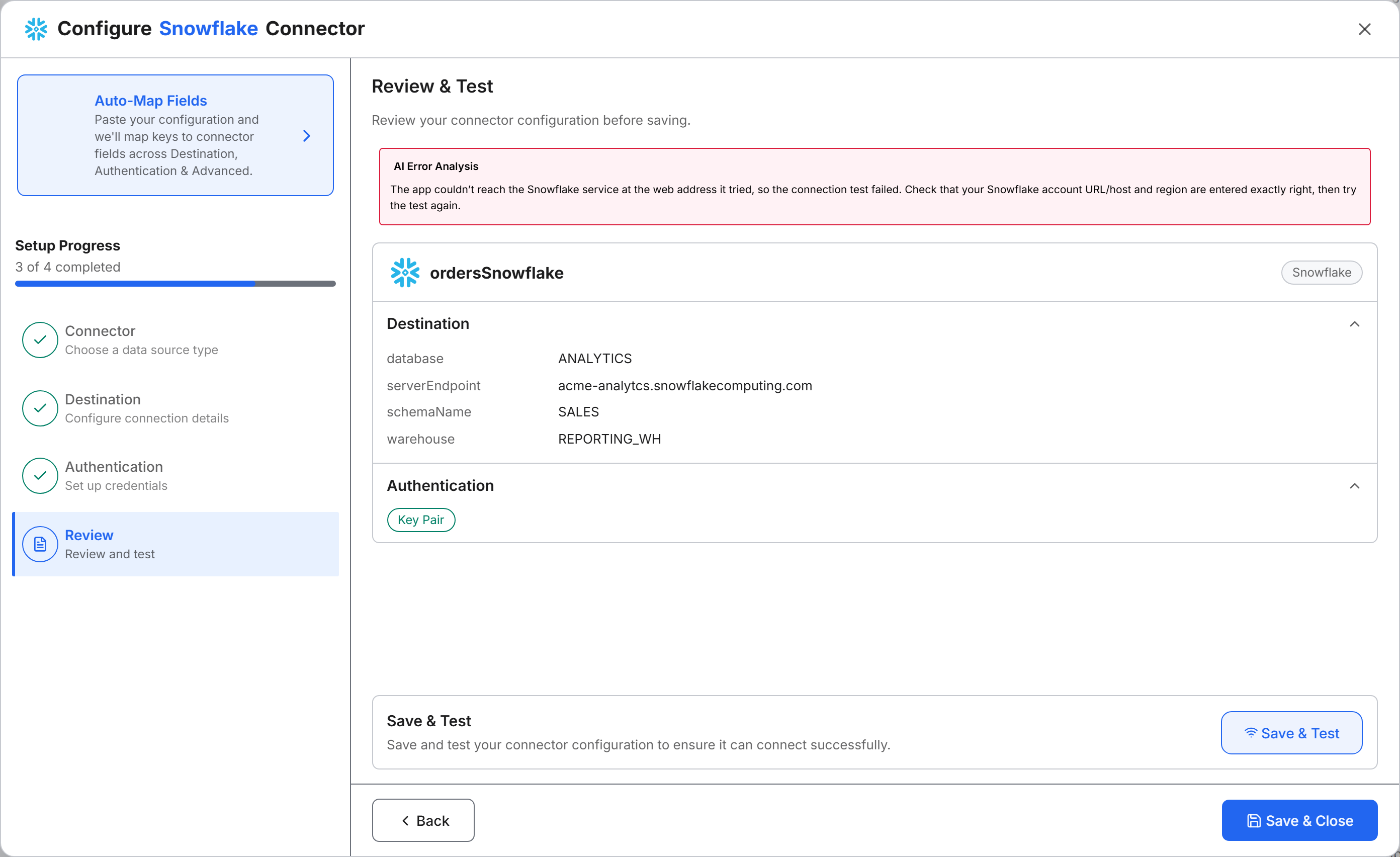
The Review step, titled Review & Test, summarizes your Destination values and the authentication method. Test the connection before you start building the pipeline:
- Select Save & Test. The wizard saves the connector and its credentials, then tests the connection to Snowflake.
- Check the result. When the test succeeds, the step shows Connection test successful. When the test fails, an AI Error Analysis message describes the likely cause.
- Select Save & Close. The SQL Source System node appears on the canvas.
Because Save & Test saves the connector first, a connector whose test failed is already saved. Correct the connector in the edit wizard, which Edit the connector describes.
Edit the connector
To change a saved connector, select its SQL Source System node on the canvas. The edit wizard opens on the Connector step. Select Destination or Authentication in the step list to change values. The Name field is read-only. To replace a stored credential, select Edit credential next to its field. Select Save & Test to test the new values, then Save Changes.
Select the source table
A SQL source collection represents one Snowflake table. Each table you select gets its own source collection and starts its own pipeline on the canvas.
Create the source collection
After you add the connector, the canvas shows a Tables placeholder node (Select tables) next to the SQL Source System node. Create the collection from the Tables placeholder node:
- Select the Tables placeholder node. The Select Source Tables page opens. The Tables list groups the tables in your database by schema.
- Select Create new and enter a name for the collection, or select Use existing to reuse a collection you already defined.
- (Optional) Enter a Description.
- Expand a schema and select a table. The preview grid shows up to the first 20 rows of the selected table.
- Select Save. A SQL Source Collection node appears.
Each collection reads one table. To read another table, on the SQL Source System node, select the Open menu button, then select Add Source Collection.
Edit the source collection
To change a collection later, select its SQL Source Collection node. The Select Source Tables page opens with the collection name in a read-only SQL Source Collection field. You can change the Description.
Describe the source table
The entity Type that mixes External lists each column of the Snowflake table and its data type. The transform reads these fields when it maps them to the target entity Type.
- Select the Source placeholder node (Describe data) connected to the SQL Source Collection node. The Define External Entity dialog opens.
- Name a new Type, or select Use an existing External Entity.
- (Optional) Enter a Description.
- Fill in the column grid. Each row has Column name, Column alias, Data type, Description, and Required. A Column alias must be alphanumeric. For a datetime column, pick the format in the datetime format selector.
- Select Infer to read the column names and types from the table.
- Select + Add Field to add a column by hand, or Delete field to remove one.
- Review the Data type of each column. For correct inference, the source values must use ISO 8601 format for datetimes and
TrueorFalsefor booleans. - Select Save. An External Entity Type node appears on the canvas.
To edit the definition as text, switch from the Schema tab to the Code tab. The Code tab shows the Type definition in C3 AI Type syntax, and your edits carry back to the Schema tab when you switch tabs.
Map fields to a target entity Type
A transform copies each source field into a target field, optionally through an expression that cleans or reshapes the value. You also create the target entity Type here.
Choose the transform type
Start from the Transform placeholder node that follows the External Entity Type node:
- Select the Transform placeholder node (Map fields). The Choose a Transform Type dialog opens.
- Select the type of transform:
- Projection: map fields with an expression per target field, without writing code. The steps in Map the fields use this type.
- Transformer: write the transform as code, for logic that a field-by-field mapping cannot express.
Map the fields
In the Map & Clean Fields dialog, map the fields:
- Select Create New Transform and enter a name, or select Use an existing Transform.
- In the target list, select Create new target. In the Choose Target Type dialog, select Entity. In the Define Target Entity dialog, name the target entity Type, define its fields, and select Save. The new Type becomes the selected target. To write to a Type that already exists, select it from the list instead.
- Select Automap Fields to map source fields to target fields with matching names.
- Edit any mapping in the Transform pane. Each row takes a source field name or an expression on source fields. Use the Filter box to find a field when the source or target has many fields.
- (Optional) Use the dialog's tools to check your mapping:
- Functions Library opens the Expression Function Library, a searchable list of functions for expressions.
- Preview Source shows sample records from the source.
- Preview Transform shows the records that your mapping produces.
- Select Save. The Transform node and the Entity Type node appear on the canvas.
Review the target entity Type
The Entity Type node is the end of the pipeline: the pipeline stores each loaded record as an instance of this entity Type. Select the node to open the Define Target Entity dialog and review or change it:
- Confirm the entity name, or select Use an existing Entity to point the pipeline at another entity Type.
- (Optional) Enter a Description.
- Review the field grid (Column name, Column alias, Data type, Description, Required). Select + Add Field to add a field.
- Select Save.
Load the data and run the pipeline
The SQL Source Collection node decides how the pipeline reads the table. Return to that node to choose the load mode, then run the pipeline. Edit properties becomes available on the node after you configure the Type that mixes External for it.
Choose Load Data and the order-by fields
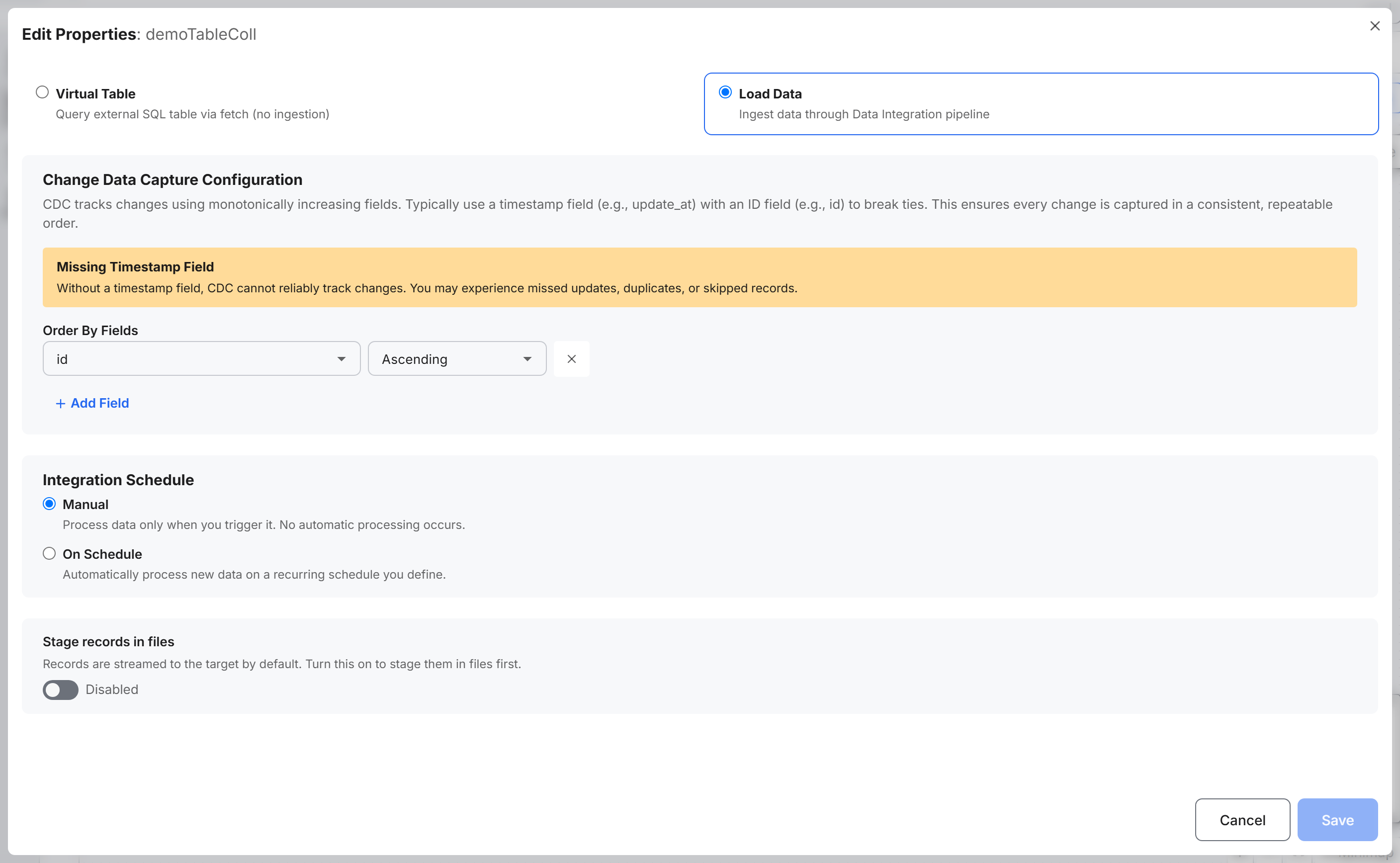
The Edit Properties dialog offers two modes:
- Virtual Table: query the Snowflake table where it is, without loading data into your application.
- Load Data: load the rows into the target entity Type through the pipeline. Use this mode to run the pipeline on this page.
With Load Data, the pipeline uses change data capture (CDC) to load only rows that are new or changed since the last run. CDC compares the Order By Fields with the highest values from the previous run. The pipeline needs at least one order-by field before it can run.
- On the SQL Source Collection node, select the three-dot Open menu button, then select Edit properties.
- Select Load Data. The Change Data Capture Configuration, Integration Schedule, and Stage records in files sections appear.
- Under Order By Fields, select a column whose value increases for every new or changed row, such as a last-updated timestamp. Keep the direction at Ascending. Select Add Field to add a second column, such as an ID, that orders rows with the same timestamp.
- Under Integration Schedule, select Manual to run the pipeline only when you start it, or On Schedule to run it on a recurring schedule.
- Select Save.
For the order-by rules, the schedule options, and staging, see Enable Change Data Capture for a SQL Source via UI.
Run the pipeline
Start the run from the SQL Source Collection node:
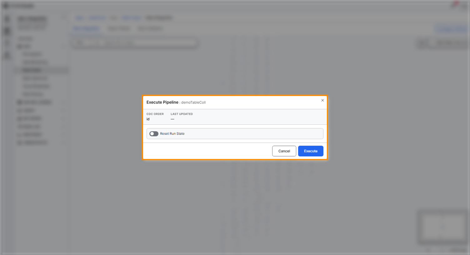
- On the SQL Source Collection node, select the Execute pipeline button (the play icon). The Execute Pipeline dialog opens. The dialog shows the saved order-by field under CDC ORDER and, under LAST UPDATED, the checkpoint: the highest order-by value that the last run loaded. Before the first run, LAST UPDATED is empty, so the first run loads the whole table.
- Select Execute.
Check the loaded data
After the run, confirm that the records arrived:
- On the SQL Source Collection node, select the Open menu button, then select View run status to see the queue activity and the Last Processed time. The run is done when the queues are empty.
- On the Entity Type node, select the Open menu button, then select View Data. The dialog lists the records that the pipeline loaded into the target entity Type.
To track pipeline runs across all source collections, see Monitor Your Data Pipeline.
Troubleshoot a failed connection test
These entries cover errors that the Review step reports.
AI Error Analysis says the account address looks wrong
AI Error Analysis reports that the app could not reach the Snowflake service at the address it tried. The Account URL has a typo or names an account that does not exist. Close the wizard and select the connector's SQL Source System node to open the edit wizard. On the Destination step, correct Account URL (for example your-account.snowflakecomputing.com), then select Save & Test again.
The wizard reports that the name already exists
After a failed test, if you change a field and select Continue on the Destination step, the wizard reports "A data source with this name already exists. Please choose a different name." Save & Test saved the connector before it tested it, so the name now belongs to that saved connector. If the saved connector's SQL Source System node shows on the canvas, select it and correct the values in the edit wizard.