Combine Multiple Sources with a Canonical via UI
You have the same business data arriving from two systems in different layouts, and you want it in one entity Type. An entity Type is the Type that stores the records in your application. Data Fusion combines different layouts with a canonical Type: a shared intermediate model that every source maps into. Each source gets its own transform into the canonical, and one more transform maps the canonical to the target entity Type. A transform maps the fields of one Type to the fields of another.
The canonical saves you from writing a separate source-to-entity mapping for every source. When you run a source's pipeline, the C3 Agentic AI Platform passes each row through every transform in the chain. The canonical therefore needs no run of its own.
The example ingests contact records from a US system that exports split names and an EU system that exports full names into one Contact entity. You connect to the storage that holds both files and create one source collection per folder. A source collection is the folder of files that a pipeline reads. Then you describe each source schema, map each source into the canonical, and map the canonical to the entity. Finally, you run both pipelines, monitor the runs, and view the merged records. The section "Add more transforms after the canonical" shows how to add a second target entity Type or a second canonical. The example uses two folders in an Amazon S3 bucket, but the same pattern works with any source type. Use your own folder, file, and Type names.
Prerequisites
Before you start, make sure you have the following:
- A C3 Agentic AI Platform environment with Data Fusion available in C3 AI Studio.
- A running C3 AI application.
- A file connector to the storage that holds both folders, saved and tested. This example uses an Amazon S3 connector. To create a file connector, follow Connect with File Source System.
- The two sample files, one folder per source. The column headers match each source schema exactly. Both files contain
bob@example.com, so you can see what happens when two sources produce the same record.
inbox/USContacts/us_contacts.csv:
firstName,lastName,email,phone
Alice,Anderson,alice@example.com,555-0101
Bob,Brown,bob@example.com,555-0102
Carol,Clark,carol@example.com,555-0103inbox/EUContacts/eu_contacts.csv:
fullName,emailAddress,telephone
Derek Dupont,derek@example.eu,+33-555-0201
Eva Engel,eva@example.eu,+49-555-0202
Bob Brown,bob@example.com,+44-555-0203
You can also create the folders and upload the files from the Set Source File Path dialog, as described in "Create the US collection".
The multi-source pipeline on the canvas
When you finish, the Data Fusion canvas shows two branches, one for each source. Each canvas element is a node, and each branch reads left to right through these nodes:
- File Source System: The connection to the storage, such as the S3 bucket. Both branches share one source system.
- File Source Collection: The folder of files that one pipeline reads (
USContactsorEUContacts). This page calls the node a source collection. - Source: The schema of one incoming row, exactly as the source exports it (
ContactSourceUSorContactSourceEU). The source schema you define here is the Source Type. - Transform: The mapping from the source schema into the canonical. Each branch has its own.
- Canonical Type: The shared model,
CanonicalContact. Both branches map into the same canonical Type. - Transform: The mapping from the canonical to the target entity Type, written one time.
- Entity Type: The target entity Type,
Contact, which stores the records.

The canvas draws the canonical, its transform, and the entity one time for each branch, so that each branch reads left to right. Nodes with the same name are the same object: editing the CanonicalContact node on one branch edits the canonical that every branch uses.
Source System node: use one connector for both folders
Both folders are in the same bucket, so one source system serves both pipelines. A source system is the connection to the external storage and holds its credentials.
- Open your application in C3 AI Studio.
- Select Data > Data Fusion. The Data Integration tab opens with the canvas.
- Find the File Source System node of the connector from the prerequisites. If you don't have a file connector, select Add Data Source, complete the Connector, Destination, Authentication, and Review steps, and select Save & Test.
The File Source System node appears on the canvas, followed by a Files placeholder node labeled Set file path.
File Source Collection nodes: create one collection per folder
Each source needs its own source collection, bound to that source's folder.
Create the US collection
Start from the Files placeholder node that follows the File Source System node:
- Select the Files placeholder node (Set file path) next to the File Source System node. If the source system already has a collection, select Open menu on the node, then Add Source Collection, instead.
- In the Choose type of source collection dialog, select Structured source collection.
- In the Set Source File Path dialog, select Create new File Source Collection and enter
USContacts. - The file browser opens in the
inboxfolder. Open theUSContactsfolder. If the folder or file does not exist yet, use Create directory and Upload files in the browser toolbar to create the folder and uploadus_contacts.csv. - Select Save.
The canvas adds the USContacts node, connected to the File Source System node, and a message confirms that the source collection was created.
Create the EU collection
After the source system has one collection, you add the next one from the node menu.
- On the File Source System node, select Open menu (the three-dot button on the node), then Add Source Collection.
- In the Choose type of source collection dialog, select Structured source collection.
- In the Set Source File Path dialog, select Create new File Source Collection and enter
EUContacts. - The file browser opens in
inbox. OpenEUContacts, or create the folder and uploadeu_contacts.csvif needed. - Select Save.
The source system now connects to two collection nodes, the start of the two branches.
Source nodes: describe each source schema
Each branch continues with a Source node (labeled Describe data until you configure it) that defines the schema of one incoming row.
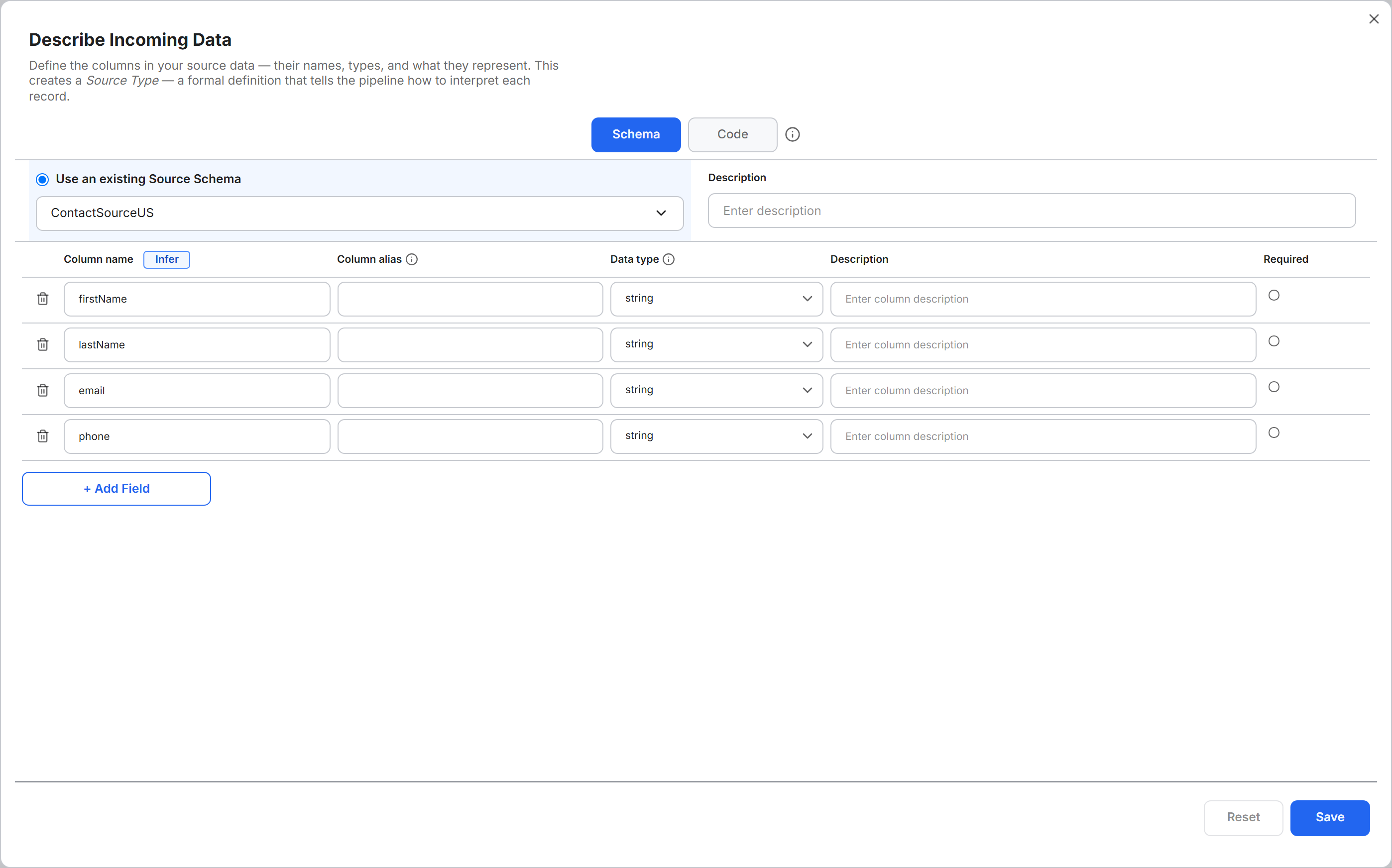
Describe the US schema
Define the US Source Type from the Source node of the US branch:
Select the Source node connected to
USContacts.In the Describe Incoming Data dialog, select Create New Source Schema and enter
ContactSourceUS.Check that the columns match the following table. The dialog reads the columns from the file when it opens. To read the columns again, select Infer.
Column name Data type firstNamestring lastNamestring emailstring phonestring Select Save.
Describe the EU schema
Define the EU Source Type the same way, with the EU columns:
Select the Source node connected to
EUContacts.In the Describe Incoming Data dialog, create a source schema named
ContactSourceEUwith these columns:Column name Data type fullNamestring emailAddressstring telephonestring Select Save.
The two schemas differ in field names and in shape, split names against full names. Each source therefore needs its own transform, and the canonical gives both transforms one target.
Transform nodes: map each source into the canonical
The first source's transform is where you create the canonical: instead of an entity, you choose a canonical Type as the target. Data Fusion offers two transform styles in the Choose a Transform Type dialog:
- Projection: Map each target field to a source field or an expression in a visual table.
- Transformer: Write the mapping as a
transformfunction in a code editor.
Projection and Transformer save different kinds of transform, so choose one style for each transform. Each mapping step gives the mapping in both styles; follow the one you chose.
Map the US source and create the canonical
Map the US Source Type and create the canonical in the same dialog:
Select the Transform placeholder node (Map fields) after the
ContactSourceUSnode.In the Choose a Transform Type dialog, select Projection or Transformer.
In the Map & Clean Fields dialog, select Create New Transform and enter
ContactSourceUS-CanonicalContact.In the Select target for transform panel, select Create new target.
In the Choose Target Type dialog, select Canonical.
In the Define Shared Model dialog, select Create New Canonical, enter
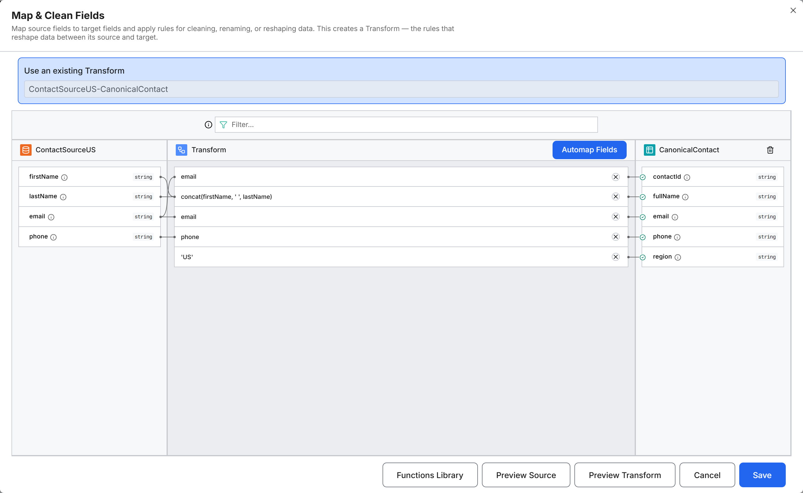
CanonicalContact, define these fields, and select Save:Column name Data type contactIdstring fullNamestring emailstring phonestring regionstring Map the source fields to the canonical fields.
With Projection, enter one expression per target field in the Transform column. Enter a source field name to copy the value, or wrap it in a function to reshape it. Automap Fields fills fields whose names match. Functions Library opens the Expression Function Library panel, which lists the functions you can use.
Target field Expression contactIdemailfullNameconcat(firstName, ' ', lastName)emailemailphonephoneregion'US'With Transformer, complete the starter
transformfunction to match the following code. To see the source and canonical schemas while you edit, open Source & Target fields.JavaScriptfunction transform(sourceObject) { return CanonicalContact.make({ contactId: sourceObject.email, fullName: sourceObject.firstName + ' ' + sourceObject.lastName, email: sourceObject.email, phone: sourceObject.phone, region: 'US', }); }Select Preview Source to inspect a sample of incoming records, and Preview Transform to check the mapped output.
Select Save.
The branch now runs from the collection through the source and the transform to a Canonical Type node, followed by a new Transform placeholder node.
Map the EU source to the existing canonical
The EU transform targets the canonical you just created, which is what joins the two branches.
Select the Transform placeholder node (Map fields) after the
ContactSourceEUnode, and select Projection or Transformer.In the Map & Clean Fields dialog, select Create New Transform and enter
ContactSourceEU-CanonicalContact.In the Select target for transform panel, search for
CanonicalContactand select Select on its row. Select the existing canonical instead of creating a second one, so both branches share it.Map the EU fields to the canonical fields.
With Projection:
Target field Expression contactIdemailAddressfullNamefullNameemailemailAddressphonetelephoneregion'EU'With Transformer:
JavaScriptfunction transform(sourceObject) { return CanonicalContact.make({ contactId: sourceObject.emailAddress, fullName: sourceObject.fullName, email: sourceObject.emailAddress, phone: sourceObject.telephone, region: 'EU', }); }The US transform builds
fullNamefrom two fields, while the EU transform copies it unchanged.Select Preview Transform to check the output, then select Save.
The EU branch now also ends at a CanonicalContact node. The canvas shows the canonical after each branch, and both nodes are the same canonical Type.
Canonical Type node: review the shared model
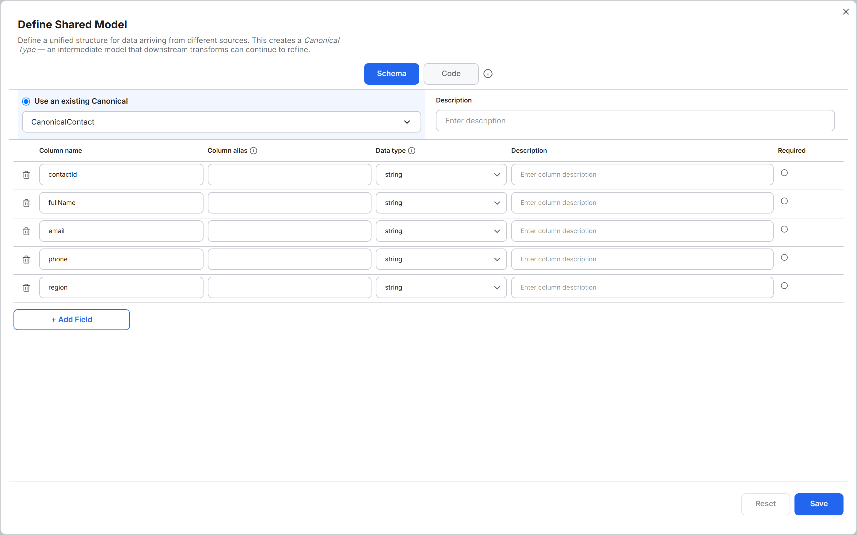
Select either CanonicalContact node to open the Define Shared Model dialog. The Schema tab lists the fields, and the Code tab shows the same definition as a Type. You don't need to edit the canonical Type:
type CanonicalContact mixes Canonical {
  contactId: string
  fullName:  string
  email:     string
  phone:     string
  region:    string
}
A canonical Type stores no records. Rows pass through the canonical Type to the next transform, and only the target entity Type stores the rows. For this reason, the Canonical Type node menu has no View Data action. You check the results at the Entity Type node.
Transform and Entity Type nodes: map the canonical to the target entity
You write the canonical-to-entity transform one time, however many sources feed the canonical.
Select the Transform placeholder node (Map fields) after either
CanonicalContactnode, and select Projection or Transformer.In the Map & Clean Fields dialog, select Create New Transform and enter
CanonicalContact-Contact.Select Create new target, then select Entity in the Choose Target Type dialog.
In the Define Target Entity dialog, define the
Contactentity with the fieldsfullName,email,phone, andregion, all of type string, and save it. An entity Type is where the platform stores the records. Every entity also has anidfield, which the target pane lists as required (*id), and an optionalnamefield.Map the canonical fields to the entity fields:
Target field Expression idcontactIdfullNamefullNameemailemailphonephoneregionregionSelect Save. The canvas adds the Entity Type node for
Contact.
The id decides which records combine. Rows from any source that produce the same id are stored as one record. The row processed later overwrites the fields it sets, and fields it leaves empty keep their earlier values. This example builds contactId from the email address, so both sources describe Bob as one contact. If two sources must never combine, prefix the id with the source name, for example concat('US-', email).
Run both pipelines
You run each source's pipeline from its collection node. The run passes every row through both transforms into the entity, so the canonical needs no separate run.
Set the integration schedule
The integration schedule decides when the collection processes its files:
- On the
USContactsnode, select Open menu, then Edit properties. - On the Integration Schedule tab, choose Manual to run the pipeline yourself, or On Schedule to process new files on a recurring schedule. For this example, keep Manual, the default. The other tabs tune parsing and processing, and you can leave them at their defaults.
- If you changed the setting, select Save. Otherwise, select Cancel.
Execute the pipeline
Start the run from the collection node:
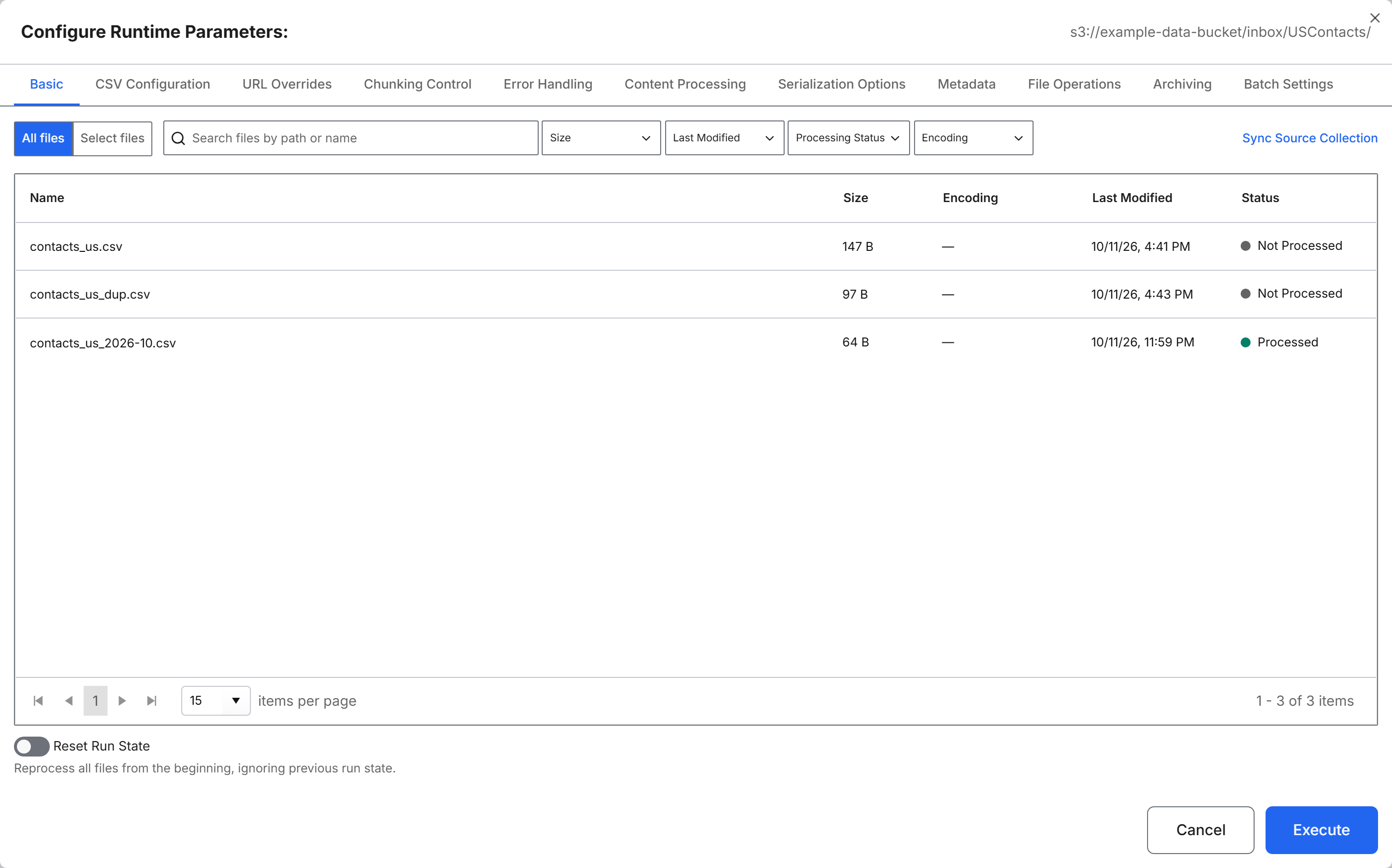
- On the
USContactsnode, select Execute pipeline (the play button on the node). The Configure Runtime Parameters dialog opens. - Leave All files selected. If the file list reads "No files found", select Sync Source Collection to list the files in the folder.
- Select Execute.
- Repeat the schedule and execute steps for the
EUContactsnode.
Monitor the runs
On each collection node, select Open menu, then View run status. The View Run Status dialog has two sections:
- File Sync Status: The sync state, Last Synced (when the platform last refreshed the file listing), and a View Batch Jobs link. The BatchQueue row counts work that is INITIALIZING, AWAITING, COMPUTING, or FAILED, and has a View Workload Management link.
- File Processing Status: The processing state, Last Processed (when the collection last processed files), and a View Data Integration Monitoring link. The SourceQueue and SourceStatusQueue rows show the same four counters, each with a View Workload Management link.
Select Refresh to update the dialog, or Close to close it.
To see each file and its row counts, select View Data Integration Monitoring. The Data Monitoring page opens. Use Search to find the collection, then select its row. The run is complete when the collection's file shows as completed with every row processed. To refresh the file listing after new files land in a folder, select Open menu, then Sync source files. A banner confirms that the sync started. The sync runs in the background and does not process the files.
For more about the monitoring page, see Monitor Your Data Pipeline.
View the merged records
Check the stored records on the Entity Type node:
- On the
ContactEntity Type node, select Open menu, then View Data. - The dialog, titled
Contact, lists the stored records. Use Filter, Include, and Order by, then select Apply, to narrow the list.
The six source rows produce five Contact records:
- Alice and Carol have region
USand names joined from first and last name. - Derek and Eva have region
EU. - Bob appears one time, with the values from the source that ran last. If you ran the EU pipeline second, Bob's record has region
EU.
Both sources produce the same id for Bob, so his rows combine into one record. You can also inspect the entity in the Object Model tab of Data Fusion.
Add more transforms after the canonical
A canonical can feed more than one transform, and a transform can target another canonical instead of an entity. Use a second transform to load a second entity from the same canonical, such as an audit entity. You can also refine the model in a second canonical before the entity. When you run a source's pipeline, each row passes through every transform in the chain in the same run. A second canonical therefore needs no run of its own.
To add a transform to a canonical that already has one:
- On the
CanonicalContactCanonical Type node, select Open menu, then Add Transform. - In Choose a Transform Type, select Projection or Transformer.
- In Map & Clean Fields, select Create New Transform and enter a name.
- Select Create new target, then choose the target type in the Choose Target Type dialog:
- Entity: define the entity in Define Target Entity, as for
Contact. - Canonical: define a second canonical in the Define Shared Model dialog. Downstream transforms can refine this intermediate model further.
- Entity: define the entity in Define Target Entity, as for
- Map the fields and select Save.
When the target is a canonical, the canvas adds a Transform placeholder node (Map fields) after it. Select the new placeholder to map the second canonical to an entity, as in the canonical-to-entity steps.
Each transform from a canonical processes every row one time. With two transforms from CanonicalContact, a three-row file produces three records in each target.
Key considerations
These rules apply to every canonical pipeline you build on the canvas:
- To add another source later, create one source collection, one source schema, and one transform into the canonical. The canonical-to-entity transform and everything after it stay unchanged.
- If your sources live in different systems, such as an S3 bucket and an Azure Blob container, create one connector per system. Each branch starts at its own source collection, so the rest of the pattern stays the same.
- Keep one transform from the canonical to each target entity Type. Every transform from the canonical runs on every row, so a second transform to the same entity processes each row twice.
- A SQL source collection in Virtual Table mode queries the table on demand and ingests no data. The collection's transforms and canonical run only when the collection loads data in Load Data mode.